24. June 2022

Weather display for LilyGO TTGO T5-4.7″ E-Paper ESP32 deployed using Arduino IDE 2.0

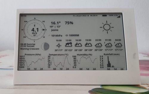
LilyGO TTGO T5-4.7″ E-Paper ESP32 is nice display which integrates ESP32, USB-C, Li-Po and 18650 accumulator support in one board. The display driver is GDEH0213B72.

One interesting use-case for the board is the Weather display.

There are several steps to get the Weather display working. Let’s walk through them.

Drivers

Linux users may skip this section since the modern kernel supports CH34x drivers.

macOS users may encounter the following error when flashing:

Failed to write to target RAM (result was ...)

It’s necessary to install the driver from https://github.com/WCHSoftGroup/ch34xser_macos.

Windows 8, 10 users may need to install https://www.wch.cn/download/CH343SER_EXE.html. Windows 11 should install the driver automatically.

Arduino IDE setup

Download Arduino IDE 2.0.

Add ESP32 boards support. Click File, click Preferences, select Settings tab. Enter the following URL to Additional boards manager URLs:

https://raw.githubusercontent.com/espressif/arduino-esp32/gh-pages/package_esp32_index.json

Click Ok. Click Tools, select Boards: …, click Boards Manager… . It will open the left pane with a list of boards. Type esp32 to Filter your search field. Find esp32 by Espressif Systems, click Install.

Preparing code

Open a terminal and clone LilyGo-EPD47 library to Arduino/libraries:

Linux:

cd ~/Arduino/libraries
git clone git@github.com:Xinyuan-LilyGO/LilyGo-EPD47.git --depth 1

macOS:

cd ~/Documents/Arduino/libraries
git clone git@github.com:Xinyuan-LilyGO/LilyGo-EPD47.git --depth 1

Make a clone LilyGo-EPD-4-7-OWM-Weather-Display to the directory with Arduino projects. The folder name with the project should match the name of the source code file OWM_EPD47_epaper_v2.5 to avoid the unnecessary step of moving the file.

Linux:

cd ~/Arduino
git clone git@github.com:Xinyuan-LilyGO/LilyGo-EPD-4-7-OWM-Weather-Display.git OWM_EPD47_epaper_v2.5

macOS:

cd ~/Documents/Arduino/
git clone git@github.com:Xinyuan-LilyGO/LilyGo-EPD-4-7-OWM-Weather-Display.git OWM_EPD47_epaper_v2.5

Open Arduino IDE 2.0, click File, select Sketchbook, click OWM_EPD47_epaper_v2.5.

The project requires ArduinoJson to build. Click Tools, click Manage libraries… . The pane with Library Manager should open, type ArduinoJson to Filter your search field. Find ArduinoJson by Benoit Blanchon, click Install.

Try to build the project.

It might fail with the following error:

.../Arduino/libraries/LilyGo-EPD47/src/rmt_pulse.c:9:24: fatal error: hal/rmt_ll.h: No such file or directory
compilation terminated.
Multiple libraries were found for "WiFiClient.h"
  Used: .../.arduino15/packages/esp32/hardware/esp32/1.0.4/libraries/WiFi
  Not used: .../arduino-1.8.13/libraries/WiFi
exit status 1

Open the file ~/Arduino/libraries/LilyGo-EPD47/src/rmt_pulse.c and comment out line 9:

/* #include <hal/rmt_ll.h> */

The project should be buildable now.

Configuring local parameters

Open file owm_credentials.h and configure ssid, password, apikey, City, Country.

The project is acquiring data from openweathermap.org. Create new free account in order to get apikey.

The project implementations contain support for power saving, so if you’re flashing in the early morning/late night, you might be surprised that nothing is on display. To change power-saving options open file OWM_EPD47_epaper_v2.5.ino and change WakeupHour to a value that suits your need.

Flashing

Connect the module. Select the board from the dropdown in the toolbar. Click Port (/dev/ttyACMx on Linux), filter for ESP32 Wrover module and click Ok.

Click the Upload arrow.

If the flashing is successful, you may enjoy the new Weather display. Congratulations!

3D printed enclosure

There are several versions of files for 3D printing. You can find them in the discussion at GitHub – LilyGo-EPD47. The picture in this article is based on model thing:4782302 printed on Original Prusa MINI+ with PET-G. The model has a few cosmetic limitations:

  • It’s not possible to keep the display standing while USB-C is connected.
  • Buttons are not completely reachable.
  • The display must be attached by a tape or other method to the stand to avoid detaching from the case.

Notes

Double-check whether the battery holder is present when ordering the board with the display from the e-shop. Even when it’s displayed on the picture, it does not mean that the battery holder or battery is part of the delivery.

When connecting by USB-C to USB-C cable, the device should light up at least a red led. If nothing is visible, rotate the USB-C connected to the board by 180 degrees or use USB-A to USB-C cable.

2. April 2022

ESP32 Arduino macOS exec: “python”: executable file not found in $PATH

Apple removed old Python 2 from macOS 12.3. Arduino ESP32 depends on Python interpreter.

Build in Arduino IDE may fail with error:

"python": executable file not found in $PATH

It’s sufficient to change name of binary to python3

Edit file

~/Library/Arduino15/packages/esp32/hardware/esp32/2.0.2/platform.txt

Change the line:

tools.gen_esp32part.cmd=python "{runtime.platform.path}/tools/gen_esp32part.py"

To line with python3:

tools.gen_esp32part.cmd=python3 "{runtime.platform.path}/tools/gen_esp32part.py"

Re-open Arduino IDE and build the project.

21. April 2017

How to connect ESP8266 to Bluemix

Connecting ESP8266 by MQTT to a server like Mosquitto is relatively easy. You need just one dependency (in platformio.ini file):

[env:d1_mini]
lib_deps =
  PubSubClient

Code for a connection is:

WiFiClient espClient;
PubSubClient mqttClient(espClient);

static void callback(char* topicChar, byte* payloadByte, unsigned int length) {
  String topic = topicChar;

  // Default size is defined in PubSubClient library and it's limited to 128
  // https://github.com/knolleary/pubsubclient
  char buf[MQTT_MAX_PACKET_SIZE];
  if (length >= MQTT_MAX_PACKET_SIZE) {
    length = MQTT_MAX_PACKET_SIZE - 1;
  }
  snprintf(buf, length + 1, "%s", payloadByte);

  String payload = String((char *)buf);
  Serial.print(payload);
}

void setup() {
  mqttClient.setServer("iot.georgik.rocks", 1883);
  mqttClient.setCallback(callback);
}

void reconnect() {
  if (mqttClient.connect("display")) {
    subscribeTopics()
  } else {
    Serial.println("Connection failed");
  }
}

Code for a subscription to topic is:

void subscribeTopics() {
  mqttClient.subscribe("some/topic/data");
}

Code for publishing to topic is:

mqttClient.publish("other/topic/data", "123");

This works fine with Mosquitto in trusted environment. You can find sample implementation in LampESP branch v0.3 in file LampMQTT.ino.

When you switch to cloud environment you have to take in consideration security model of the cloud. E.g. Microsoft Azure IoT Hub does not support direct communication between devices. Similar limitation is true also for IBM Bluemix. The architecture of messaging must be little bit different.

How to change the code to connect to IBM Bluemix?

First of all you need to create an account in IBM Bluemix. There is 30 day trial. Then you can use part of services for free, but you have to enter your credit card. The free 370 GB-hours is sufficient to run 512 MB virtual machine during whole month for free.

Then you have to create “Internet of Things Platform” service. This service is available only in regions US and United Kingdom. The region Germany does not support this service yet. Once the service is running, go to Dashboard for your service.

You’ll be redirected to URL like: https://ORG-ID.internetofthings.ibmcloud.com/dashboard/#/boards/

There you’ll see IBM Watson IoT Platform Dashboard. Go to Devices.

Click “+ Add Device” button. Then click “Create device type”.

Click “Create device type”.

Set name e.g. to ESP8266 and proceed with registration of device type.

Once the type is ready you can define device. Click “+ Add device”. Select your type ESP8266 from drop down. Now careful!

The Next button is in lower right corner. It seems that UX engineers were not validating the interface.

Fill in the name of the device and description.

You can skip Metadata. Leave Security set to Auto-generated authentication token.

Skip summary and click Add.

Now you’ll see page with Device. The most important part is section with Authentication token.

The cloud is ready. Now it is necessary to update the code. There is a small gotcha in the server name. If you look at Watson dashboard you might think that’s the hostname for MQTT: ORG-ID.internetofthings.ibmcloud.com. You have to inject subdomain “messaging”. The correct hostname is: ORG-ID.messaging.internetofthings.ibmcloud.com.

...
void setup() {
  mqttClient.setServer("ORG-ID.messaging.internetofthings.ibmcloud.com", 1883);
  mqttClient.setCallback(callback);
}
...

The next important step is to add token which will be used to establish a session between the device and cloud. This is a little bit tricky. You’ll need three parameters which will be composed in the following fashion and supplied to connect method of PubSubClient:

  • id = “d:ORG-ID:ESP8266:DEVICE-NAME”
  • username = “use-token-auth”
  • password = “TOKEN-FROM-DEVICE-PAGE”
void reconnect() {
  if (mqttClient.connect(id, username, password)) {
    subscribeTopics()

In the case of cloud version of MQTT you could not subscribe or publish just to any random topic. You have to follow the format. In the case of subscription to command you have to use following topic: iot-2/cmd/COMMAND/fmt/json. Replace COMMAND, by any of your commands that the device should receive.

void subscribeTopics() {
  mqttClient.subscribe("iot-2/cmd/COMMAND/fmt/json");
}

To publish the device status there is also special topic:

mqttClient.publish("iot-2/evt/status/fmt/json", "{\"d\":{\"value\":\"online\"}}");

Now you’re ready to connect to the Bluemix cloud. If you experience any problems, just go to device detail and find Connection log.

Now you can connect Node-RED or other tools and communicate with the device. You can find working implementation at LampESP v0.4 project.

Let’s a make summary. There are three gotchas:

  • MQTT must be connected to subdomain: ORG-ID.messaging.internetofthings.ibmcloud.com
  • Subscription and publishing must follow specific format of topic name
  • Auth information must be composed in precisely

2. April 2017

Custom font for OLED display connected to ESP8266 via SPI

Small OLED displays can easily extend the functionality of ESP8266.

I made an experiment with 128×64 OLED display from Com-Four.

The first challenge was how to connect the display to ESP8266. The recommended way for high performance is to use Serial Peripheral Interface Bus (SPI). The advantage of this approach is the speed, the disadvantage is that it will take more pins.

The display could be connected in following way (also described in the example of ESP8266_SD1306 library):

ESP8266 - SD1306
GND     - GND
3V      - VDD
D5      - SCK (also known as CLK)
D7      - SDA (also known as MOSI/DOUT)
D0      - RES
D2      - DC
D8      - CS

If you’re using PlatformIO, just add ESP8266_SD1306 library to dependencies in platfromio.ini:

lib_deps =
 ESP8266_SSD1306

Now you can run any example from Squix78 library. The library contains 3 sizes of Arial font: 10, 16 and 24px.

My goal was to display temperature from Observatory in Brno. Retrieving temperature and sending it to MQTT for ESP8266 was quite easy.

#!/usr/bin/env python3

import paho.mqtt.publish as publish

import urllib.request
f = urllib.request.urlopen('http://www.hvezdarna.cz/meteo/lastmeteodata')
content = f.read().decode('utf-8')

items = content.split(' ')

publish.single('/home/monitor/display/0', items[4], hostname='localhost')

I used default Arial 24 font. The problem was that the number was too small and barely readable from a distance. Luckily Daniel Eichhorn published great online tool which is able to generate font of any size for OLED display: http://oleddisplay.squix.ch.

My first attempt was to generate Roboto Light 54px font. It was working, just number 4 was not visible. I discovered a bug in the generator, that too big font will overflow default size of char in the jump table.

After several attempts I’ve found the right font for me DejaVu Sans 52px. This font was far more readable.

The last touch to make the font more readable was to tune down contrast little bit by the command:

display.setContrast(10);

I can definitely recommend this type of OLED display. It has good readability even during a sunny day. The code is available at GitHub in LampESP project.

6. November 2016

Controlling lamp with ESP8266 via WiFi by Android Widget

Two weeks ago I made research about available Smart Home Power Sockets. The result was not very positive.

Week ago I discovered talk about ES8266 which seemed to be the right solution.

And what about this week?

I happy to report success. I am able to control the lamp from mobile phone. :-)

This week I bought WeMos D1 Mini WiFi ESP8266 and relay. Together with friend we soldered few pins and wrote some code. The solution was working immediately after we plugged it into a wall.

Here is the result:

20161105_esp8266-with-relay

Code for Arduino is derrived from esp8266learning.com:

//This example will set up a static IP - in this case 192.168.1.50
 
#include <ESP8266WiFi.h>

const int relayPin = D1;
const int chipSelect = D8;
const char* ssid = "MYSSID";
const char* password = "SECRET";
 
WiFiServer server(80);
IPAddress ip(192, 168, 1, 50); // where xx is the desired IP Address
IPAddress gateway(192, 168, 1, 1); // set gateway to match your network
 
void setup() {
  Serial.begin(115200);
  delay(10);
 
  pinMode(relayPin, OUTPUT);
 
  Serial.print(F("Setting static ip to : "));
  Serial.println(ip);
 
  // Connect to WiFi network
  Serial.println();
  Serial.println();
  Serial.print("Connecting to ");
  Serial.println(ssid);
  IPAddress subnet(255, 255, 255, 0); // set subnet mask to match your network
  WiFi.config(ip, gateway, subnet); 
  WiFi.begin(ssid, password);
 
  while (WiFi.status() != WL_CONNECTED) {
    delay(500);
    Serial.print(".");
  }
  Serial.println("");
  Serial.println("WiFi connected");
 
  // Start the server
  server.begin();
  Serial.println("Server started");
 
  // Print the IP address
  Serial.print("Use this URL : ");
  Serial.print("http://");
  Serial.print(WiFi.localIP());
  Serial.println("/");
}
 
void loop() {
  // Check if a client has connected
  WiFiClient client = server.available();
  if (!client) {
    return;
  }
 
  // Wait until the client sends some data
  Serial.println("new client");
  while(!client.available()){
    delay(1);
  }
 
  // Read the first line of the request
  String request = client.readStringUntil('\r');
  Serial.println(request);
  client.flush();
 
  // Match the request
 
  int value = LOW;
  if (request.indexOf("/relay=on") != -1) {
    digitalWrite(relayPin, HIGH);
    value = HIGH;
  } 
  if (request.indexOf("/relay=off") != -1){
    digitalWrite(relayPin, LOW);
    value = LOW;
  }
 
  // Return the response
  client.println("HTTP/1.1 200 OK");
  client.println("Content-Type: text/html");
  client.println(""); //  do not forget this one
  client.println("<!DOCTYPE HTML>");
  client.println("<html>");
 
  client.print("Led pin is now: ");
 
  if(value == HIGH) {
    client.print("On");  
  } else {
    client.print("Off");
  }
  client.println("<br><br>");
  client.println("<a href=\"/relay=on\">Relay ON</a><br>");
  client.println("Click <a href=\"/relay=off\">Relay OFF</a>");
  client.println("</html>");
 
  delay(1);
  Serial.println("Client disconnected");
  Serial.println("");
}

That was the easy part. I was able to control relay directly from mobile phone via web browser which was not very convenient. The widget would serve better.

Writing a widget for Android was real challenge. There is very little documentation about it and even Android Studio does not contain template for writing widget. I spent several hours learning how widget works. It is very different from common application.

The very first gotcha that costed me more than a hour was very common problem with builds:

Error:(3) Error retrieving parent for item: No resource found that matches the given name 'android:TextAppearance.Material.Widget.Button.Inverse'.

Yes, it is very clear where is the problem. Or not? :)

It is necessary to fix build.gradle and set proper version of compile dependency. In my case I was targeting API 22, but appcompat was set to 23:

dependencies {
    compile 'com.android.support:appcompat-v7:22.1.1'
}

The real fun begins with the widget code. I cobbled together several chunks of code. Primary source was Obaro’s SimpleAndroidWidget and android-async-http.

Here is the very crude code for Android:

package com.sample.foo.simplewidget;

import android.app.PendingIntent;
import android.appwidget.AppWidgetManager;
import android.appwidget.AppWidgetProvider;
import android.content.Context;
import android.content.Intent;
import android.content.SharedPreferences;
import android.widget.RemoteViews;

import com.loopj.android.http.AsyncHttpClient;
import com.loopj.android.http.AsyncHttpResponseHandler;

import cz.msebera.android.httpclient.Header;

public class SimpleWidgetProvider extends AppWidgetProvider {

    private void getHttpRequest(String state) {
        AsyncHttpClient asyncClient = new AsyncHttpClient();
        asyncClient.get("http://192.168.1.50/relay=" + state, new AsyncHttpResponseHandler() {
            @Override
            public void onStart() {
            }

            @Override
            public void onSuccess(int statusCode, Header[] headers, byte[] responseBody) {

            }

            @Override
            public void onFailure(int statusCode, Header[] headers, byte[] responseBody, Throwable error) {

            }

        });
    }

    @Override
    public void onUpdate(Context context, AppWidgetManager appWidgetManager, int[] appWidgetIds) {
        final int count = appWidgetIds.length;

        for (int i = 0; i < count; i++) {
            int widgetId = appWidgetIds[i];
            String value = "off";
            SharedPreferences prefs = context.getSharedPreferences("LampApp", 0);
            boolean isRelayEnabled = prefs.getBoolean("relayState", false);
            isRelayEnabled = !isRelayEnabled;
            SharedPreferences.Editor editor = prefs.edit();
            editor.putBoolean("relayState", isRelayEnabled);
            editor.commit();

            if (isRelayEnabled) {
                value = "on";
            }
            getHttpRequest(value);


            RemoteViews remoteViews = new RemoteViews(context.getPackageName(),
                    R.layout.simple_widget);
            remoteViews.setTextViewText(R.id.textView, value.toUpperCase());

            Intent intent = new Intent(context, SimpleWidgetProvider.class);
            intent.setAction(AppWidgetManager.ACTION_APPWIDGET_UPDATE);
            intent.putExtra(AppWidgetManager.EXTRA_APPWIDGET_IDS, appWidgetIds);

            PendingIntent pendingIntent = PendingIntent.getBroadcast(context,
                    0, intent, PendingIntent.FLAG_UPDATE_CURRENT);
            remoteViews.setOnClickPendingIntent(R.id.actionButton, pendingIntent);

            appWidgetManager.updateAppWidget(widgetId, remoteViews);
        }
    }


}

That’s not all. When you want to create widget you need to define also special handling in AndroidManifest.xml

<manifest xmlns:android="http://schemas.android.com/apk/res/android"
    package="com.sample.foo.simplewidget">

    <uses-permission android:name="android.permission.INTERNET" />

    <application android:allowBackup="true" android:label="@string/app_name"
        android:icon="@mipmap/ic_launcher" android:theme="@style/AppTheme">

        <receiver android:name="SimpleWidgetProvider" >
            <intent-filter>
                <action android:name="android.appwidget.action.APPWIDGET_UPDATE" />
            </intent-filter>
            <meta-data android:name="android.appwidget.provider"
                android:resource="@xml/simple_widget_info" />
        </receiver>

    </application>

</manifest>

Even that is not enough. You’ll need several small files in res directory including graphics. I won’t describe them here. You can download it from GitHub repo georgik/LampAndroidWidget.

The result?

widget-android

It works perfectly on Samsung Galaxy S5 Neo, but for some reason I was not able to display this widget on Lenovo K5. If you have any idea why Lenovo K5 has such issue, let me know.

I also discovered a bug in the code of widget. When you have more than one widget it starts turning on and off the relay several times depending on number of widgets ;-)

The solution is ok for the time being. I’m already thinking about using MQTT and Node-Red which was discussed this weekend at OpenAlt conference in Brno by guys from McGayver Bastlíři SH.