18. July 2020

How to connect ESP8266 Wemos D1 to motor shield over I2C with MicroPython

ESP8266 Wemos D1 board has extension shield TB6612FNG which provides a connection to two motors.

The simplest way to get motors running is to connect the shield to ESP8266 and provide instructions to MicroPython repl so that ESP8266 can send instructions over I2C to TB6612FNG.

The first requirement to get the motor running is to have d1motor library.

You can download ZIP with patched d1motor library and sample code from here.

Original d1motor is available here: https://bitbucket.org/thesheep/micropython-d1motor/src/default/d1motor.py

Use rshell to copy the library on ESP8266 board.

unzip d1motor.zip
cd d1motor
rshell -p /dev/ttyUSB0
cp d1motor.py /pyboard/

Then start repl so that it’s possible to communicate with motor shield. You can exit repl by CTRL+X:

cd /pyboard/
repl

Insert following code:

import d1motor
from machine import I2C, Pin
i2c = I2C(-1, Pin(5), Pin(4), freq=100000)
m0 = d1motor.Motor(0, i2c)
m1 = d1motor.Motor(1, i2c)
m0.speed(5000)

By this moment motor should start roaring and rotating. Well, that would be the happy day scenario. There are several gotchas which you may encounter.

Gotcha #1 OSError: [Errno 19] ENODEV

The code might throw ENODEV error without further explanation of what went wrong. The error means that ESP8266 was not able to find motor board via I2C. You can verify the problem by entering code:

from machine import I2C, Pin
i2c = I2C(-1, Pin(5), Pin(4), freq=100000)
i2c.scan()

The correct result should be array with 48 which is 0x30.

[48]

If you get just empty array then the boards are not able to talk over I2C:

 [ ]

The most common reason for the problem is buggy version firmware in STM32F030. You must flash it according to instructions from hackday.io.

You will need UBS2TTL module to perform flashing.

Download patched firmware: motor_shield.bin

Connect by single wire RTS with 3V3 PIN – they’re next to each other.

Connect folling wires on main part of board (not part with RTS):

GND - GND
3V3 - 3V3 VCC on USB2TTL
D2 - TX
D1 - RX

Install stm32flash:

sudo apt-get install stm32flash

Unlock and flash the shield:

stm32flash /dev/ttyUSB0 -k
stm32flash /dev/ttyUSB0 -u
stm32flash /dev/ttyUSB0 -v -w motor_shield.bin

After flashing unplug wires and connect the shield back to ESP8266. Run I2C scan again and you should get the correct result:

from machine import I2C, Pin
i2c = I2C(-1, Pin(5), Pin(4), freq=100000)
i2c.scan()

[48]

Gotcha #2 Standby mode not controlled by I2C

Even after the first correction, the motors might not move and there is no voltage on A1-2 or B1-2. The problem is most likely caused by Standby mode.

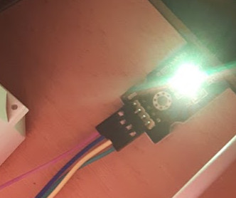
Check your board and you should see STBY with 3 pins and with marking I2C and IO. You need to solder top and middle pin to enable I2C control of Standby mode. Solder them and plug the board again. Now motors should start to move.

Gotcha #3 Incorrect frequency

There might be a third reason why motors are not moving: Incorrect frequency of communication via I2C. Double-check the number. One missing zero might cause the problem.

Not working configuration:

i2c = I2C(-1, Pin(5), Pin(4), freq=10000)

Working configuration:

i2c = I2C(-1, Pin(5), Pin(4), freq=100000)

Does it work? Congratulations.

Big thanks to community Radomir Dopieralski for d1motor.py, aarn_a and Matrix User for hints about Standby mode.

9. April 2017

How to edit font for OLED display SD1306

In the previous article, I’ve described how to generate custom font for OLED display like SD1306.

Meanwhile, I’ve discovered that number eight and number zero are hard to distinguish when reading from a distance, because of the dot inside the number zero.

I decided to remove the dot from number zero in order to make the font more readable. But how to do it?

Font generated from Squix’s generator is stored in form of source code. That makes it possible to edit. Just the stream of hexadecimal numbers is not very readable for a human.

Here is a small trick. Open the file in Vim in a terminal window. Search for string 0x00 which represents an area with no pixels. Vim should highlight all the occurences of 0x00. If you can’t see the highlight type command:

:set hlsearch

Start shrinking the window of the terminal and you should see that pattern begins to emerge.

When you hit the correct length of a line you should see the number clearly.

Numbers could be rotated, like number seven:

Change the font rebuild the code and the result looks like this:

2. April 2017

Custom font for OLED display connected to ESP8266 via SPI

Small OLED displays can easily extend the functionality of ESP8266.

I made an experiment with 128×64 OLED display from Com-Four.

The first challenge was how to connect the display to ESP8266. The recommended way for high performance is to use Serial Peripheral Interface Bus (SPI). The advantage of this approach is the speed, the disadvantage is that it will take more pins.

The display could be connected in following way (also described in the example of ESP8266_SD1306 library):

ESP8266 - SD1306
GND     - GND
3V      - VDD
D5      - SCK (also known as CLK)
D7      - SDA (also known as MOSI/DOUT)
D0      - RES
D2      - DC
D8      - CS

If you’re using PlatformIO, just add ESP8266_SD1306 library to dependencies in platfromio.ini:

lib_deps =
 ESP8266_SSD1306

Now you can run any example from Squix78 library. The library contains 3 sizes of Arial font: 10, 16 and 24px.

My goal was to display temperature from Observatory in Brno. Retrieving temperature and sending it to MQTT for ESP8266 was quite easy.

#!/usr/bin/env python3

import paho.mqtt.publish as publish

import urllib.request
f = urllib.request.urlopen('http://www.hvezdarna.cz/meteo/lastmeteodata')
content = f.read().decode('utf-8')

items = content.split(' ')

publish.single('/home/monitor/display/0', items[4], hostname='localhost')

I used default Arial 24 font. The problem was that the number was too small and barely readable from a distance. Luckily Daniel Eichhorn published great online tool which is able to generate font of any size for OLED display: http://oleddisplay.squix.ch.

My first attempt was to generate Roboto Light 54px font. It was working, just number 4 was not visible. I discovered a bug in the generator, that too big font will overflow default size of char in the jump table.

After several attempts I’ve found the right font for me DejaVu Sans 52px. This font was far more readable.

The last touch to make the font more readable was to tune down contrast little bit by the command:

display.setContrast(10);

I can definitely recommend this type of OLED display. It has good readability even during a sunny day. The code is available at GitHub in LampESP project.

20. February 2017

How to send command from Python via MQTT to RGB LED connected to ESP8266

I’ve described how to send server load as a number to MQTT in the previous article. The number could be then translated via Node-RED to command for LampESP with RGB LED. The result is simple. LED indicates server load by displaying different colors.

The other option is to deliver color command directly from the server using Python.

Just install paho-mqtt:

pip install paho-mqtt

Here is small snippet of Python code (publish_server_load.py):

#!/usr/bin/env python3

import paho.mqtt.publish as publish
import os

color = 'red'
load = os.getloadavg()[0]
if load < 0.7:
    color = 'black'
elif load < 1.5:
    color = 'blue'
elif load < 3:
    color = 'green'
elif load < 7:
    color = 'orange'

publish.single('/server/monitoring/command', color, hostname='iot.sinusgear.com')

ESP should listen to /server/monitoring. Code of LampESP 0.3 is available at GitHub.

Put this code into crontab

* * * * * /usr/local/bin/publish_server_load.py

If you’re using virtualenv the command should be:

* * * * * /opt/my-python-env3/bin/python /usr/local/bin/publish_server_load.py

1. December 2016

ESP8266 WiFiManager gotchas

Thanks to PlatformIO it is very easy to add further functionality from libraries to the code for ESP8266. When you need to install library, just start Library Manager from ide and type:

pio lib install WiFiManager

PlatformIO will resolve dependencies and download all necessary stuff. Even better option is to add dependency to platformio.ini file:

[env:d1_mini]
platform = espressif8266
board = d1_mini
framework = arduino
lib_deps =
  ArduinoJson
  esp8266_mdns
  PubSubClient
  WiFiManager

PlatformIO will manage the installation after you save the file. That is very neat.

Then new problems occurred when I started with integration of WiFiManager. Do not take me wrong. WiFiManager is very handy library, but you may experience some tricky issues.

The first problem that I hit was that WiFiManager interface was not visible at 192.168.4.1 port 80. ESP was apparently running in AP mode for configuration, but there was no web interface. This issue was caused by this line in my code:

ESP8266WebServer server(80);

I had web server in the main code before I merged the code from WiFiManager. Web server was serving simple REST API for controlling relay. Unfortunately this construct blocked the port so the AutoConnect web server. The server was not able to bind the port. Solution was simple. It was sufficient to instantiate web server after WiFi was working.

The second problem was that AutoConnect from WiFiManager was always turning in AP mode. I was hunting the problem for several hours without any result. One idea was that WiFiManager is not saving the password. That was not true. Other idea was that the memory is corrupted and reformat would help. Unfortunately it didn’t. I gave up.

That solved the problem. Seriously. I gave up and that solved the problem. I let the device running and then ding. It was online. For some strange reason ESP8266 was not able to establish connection with particular WiFi router at first shot. Then it turned on AP mode and after timeout of Config Portal it connected to the WiFi network. Remedy? Just shorten ConfigPortalTimeout:

wifiManager.setConfigPortalTimeout(60);

The third problem was that Config Portal was not displaying information stored as extra custom parameters. I stored there host name of MQTT broker and other options so they won’t be hardcoded. The problem was caused by WiFiManagerParameter constructed in global scope. Issue was similar the first problem with web server.

Solution was to move construction of WiFiManagerParameter to the method after loading configuration values from file config.json stored on file system.

File configFile = SPIFFS.open("/config.json", "r");
...
WiFiManagerParameter custom_mqtt_host("mqtt_host", "MQTT host", configMqttHost, 40);

After resolving these issues WiFiManager is working and it is possible to set values for configuration via Config Portal and there is no need to hardcode them anymore.

Original code is stored at GitHub – LampESP branch v0.1. The new version is at Github – LampESP branch master. I made also small refactoring and the functionality was divided into smaller files which resembles modules for better code maintenance.